Window Line
Window Line
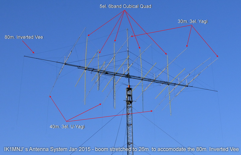
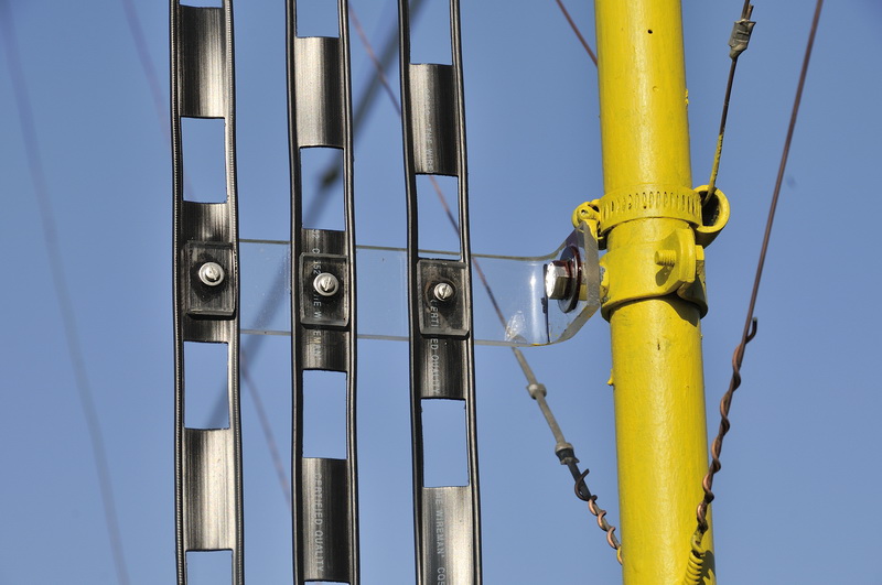
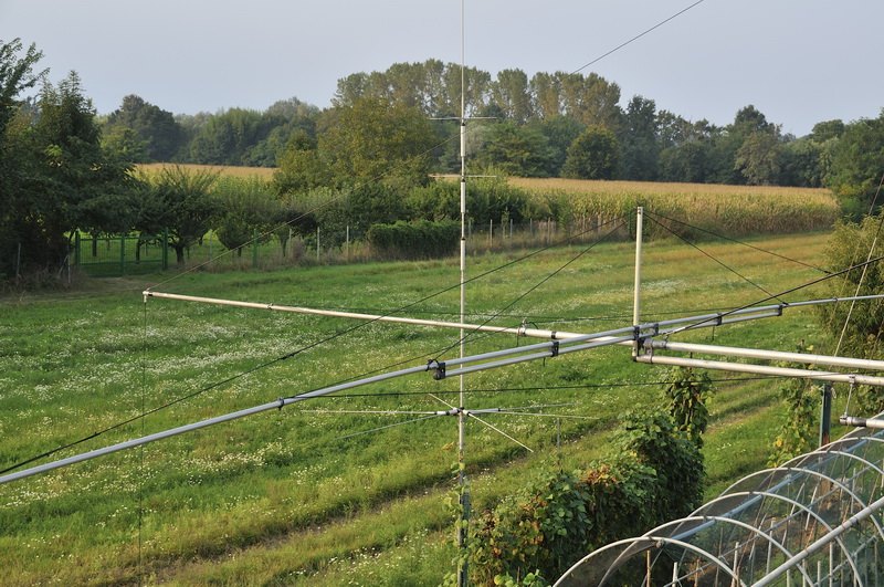
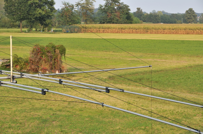
Have always had a desire and will sooner or later to get always a perfect match on the various bands both in the lower part cw that in the upper part phone and with possible lower losses in the supply line from the point of supply of various bands until the shack, a kind of dynamic antenna but I think even better, here' s the project to replace the various systems of adaptation up to now used on the various points of power antennas that were made with gamma match for bands of 6/10/12/15 and 17 meters, with impedance transformer for 20m. and 1: 1 balun on yagi of 30 and 40m., a good part of the Summer 2014 I passed by implementing the necessary changes, then dismantling virtually all feed line in each band 6> 40m. made with RG213 coax cable up to the switch including 8-way coax switch place on the mast and from this the descent towards the shack, done with Coax Pope H 100 (about 45 meters); did this i have made the brackets Plexiglas 5 mm thickness suitable for spacing three 450 homs ladder line between them and towards the arm of the Quad Antenna and in general by the metal masses boom, mast etc.
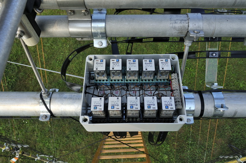
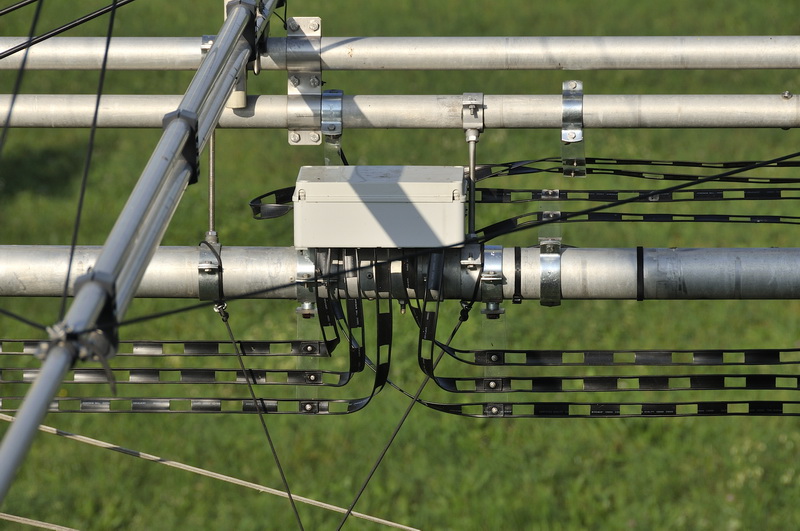
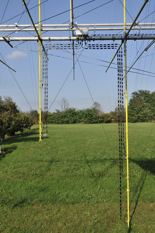
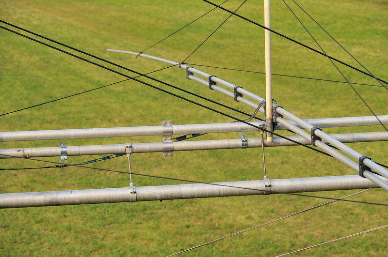
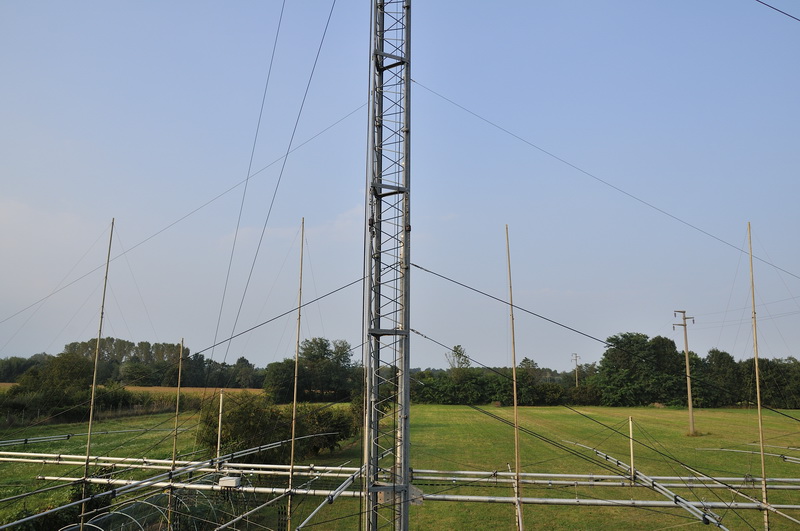
I built then switch to 10-way ribbon 450 homs and placing this time on the boom midway between elemernt 6/10/12 and 15/17/20m. and meters, the radiating elements 30 and 40m. are on the opposite side of the boom so the window line that go to the switch 450 homs are longer but do not create problems, the old switch always homebuilt was no longer suitable as used inputs and output with the PL, I used for this new relay plug bipolar Omron 16 Amp considering my maximum output power of 500 watts in supporting these relays are more than suitable, from the switch comes with window line 450 homs duly distanced from the boom and the mast down to the shack where it ends on a 3 Kw 4:1 baloon, 6>160 m., placed on the outside wall of the shack itself and from here comes into the shack to the Automatic Tuner J.W.Miller Mod. AT2500 with a piece of 4 meters of RG213 coax, after various tests on the various bands made with various weather conditions have given excellent results, with the rain there are slight variations in agreement to do but nothing to worry about, then I have to say that the changes made have given a site in exceptional, beyond expectations on all bands, especially on the higher ones, in conditions of good propagation signals received are very strong, the certainty of always having a ros 1: 1 with losses to a minimum on the line wherever you move on the bands is very rewarding; in waiting to install the new tower wich will support for 4 phased vertical dipoles for 80m, temporarily I added a kind of inverted Vee for 80 meters, feed the same way with ladder line 450 homs and arranged from the top of the mast which is located 32 meters high and drops to Vee on the ends of the boom (duly stretched to 4.20 meters per side, now the boom is 26 m. tot) the Vee which is formed is quite squashed , the excess wire dipole are left dangling to the ground by the end of the boom (as I did in the 3 el. U-Yagi of 40 meters).
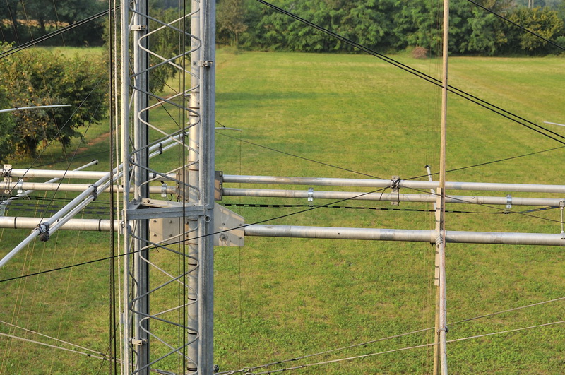
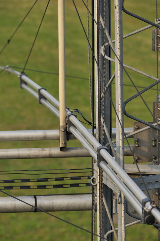
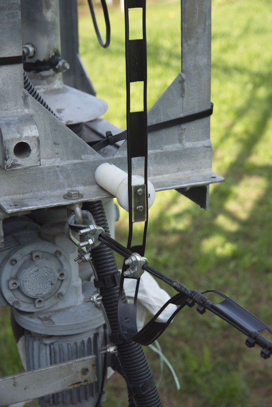
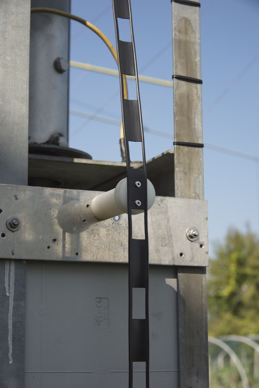
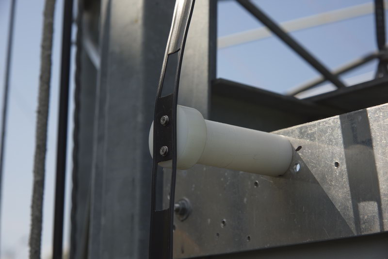
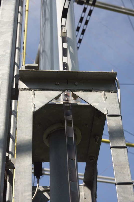
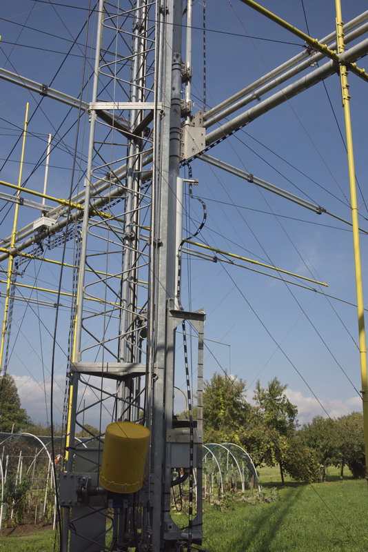
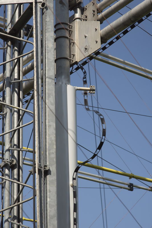
The problems encountered during these changes were different especially two: 1 point, while orientation of' antenna on 360 degrees sure that the ladder line 450 homs rotates around the mast without getting too close to the mast it self but remains at a distance security of at least 8-10 cm, which I did by mounting around a piece of pVC pipe of 160 mm diameter fixed around the mast, and appropriately setting the strip in the two strategic points allowing the same rotation of 360 degrees, about it this summer already have in mind the changes to be done to improve the system, * the 2nd point, the need to have the total length of the ladder line 450 homs of a total length that is not resonant on the respective bands to not to have problems fall of radiofrequency in the shack, which is not easy to obtain, measures not resonant on HF (50 MHz apart) that are right for me are from 31.8 to 33.6 meters and from 42.3 to 44.1 meters, as physically the measures of the pieces of window line 450 homs ranging from the respective feed points of each band to the switch are inevitably different, anywhere you put the switch antenna, these measures adding to window line down to 450 homs in station must fall for every single band in the measures I mentioned above, can I have reached a compromise of this measure total fact of the strong fall of radiofrequency in 6 meters, slightly in 12/15 m cw, little bit more in 30 meters, about it next summer have in mind the changes to be done to improve the system, through the relays to insert pieces of different lengths of window line 450 homs, we will see what to do, the same way I do precise measurements on the different values of the antennas at the ends of the window line in shack, to properly evaluate the situation and if necessary replace the 4: 1 balun with a 9: 1, which seems more appropriate, stay tuned for news on progress on these issues, thanks everyone for their patience had in reading me, greetings and 73 ' de Enrico IK1MNJ .
Added Note 17Apr2016
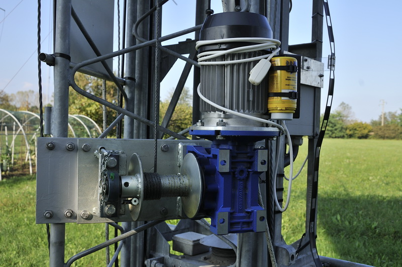
Improved arrangement of the window line around the mast at the point of rotation.
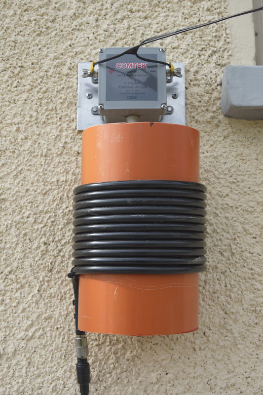
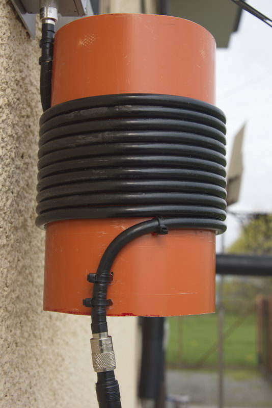
Construction of a balun to avoid little RF in the shack (*see here above) 11 turns (6 mt.) of Coaxial Cable RG 213 on a piece of PVC pipe 16 cm in diameter
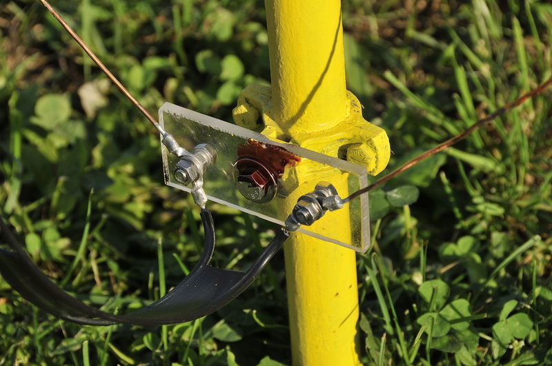
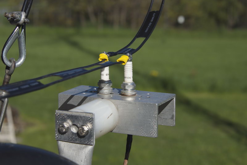
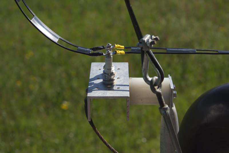
Construction of Ladder-Line Arc-Shunts, using 2 spark plugs.
( see pictures slideshow )